
AeroFlight 101
How does an arrow fly? We at Firenock believe that this is the million dollar question. Whether you’re a recreational or competitive archer, how your arrow flies, or more specifically, how to ensure your arrow flies where you want it to, is what matters the most. Below, we've broken down some essential factors about arrow flight—AeroFlight.
The Null Point
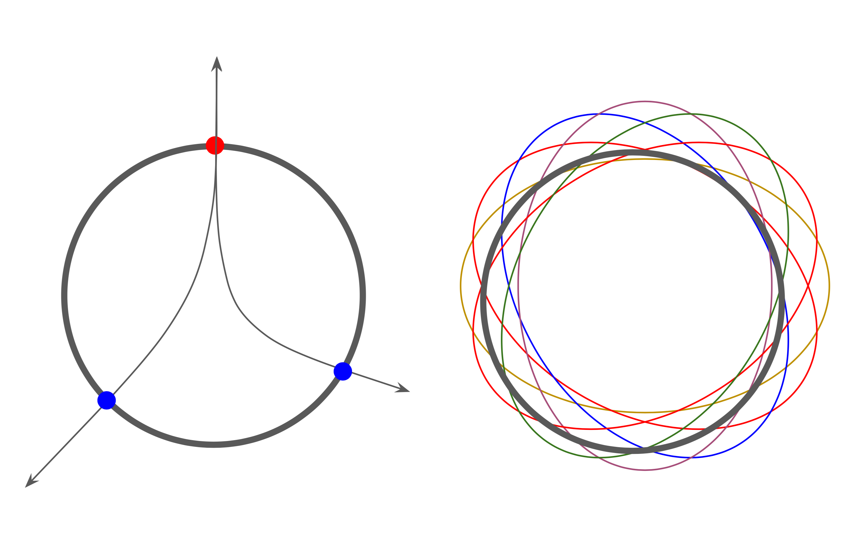
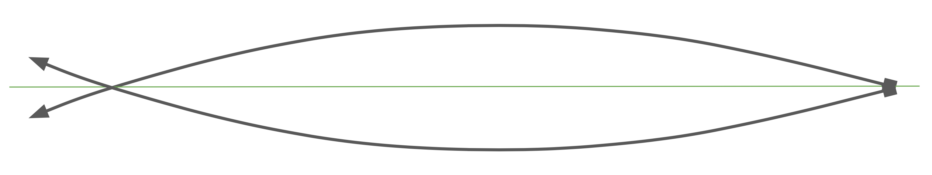
The factor that matters the most before launch is something called the null point or “node.” The node of an arrow is the unique point (red dot) where no vertical or horizontal (line in green) movement occurs at initial launch. But [1] how do you find it, [2] why should you find it, and [3] what do you do with it after you find it?
1. Loosely hold a complete arrow by its nock end and knock it on a hard surface from a few inches away until you hear a solid shift in tone. The arrow should also not bounce when the node is located.
2. Your arrow rest should match up with the node when you pull back. That way, there will be a minimal chance of your arrow skewing away from true center at initial launch.
3. To take full advantage of your arrow’s inherited null point, use it when tuning your archery setup today.
Rotation versus Torque-Induced Procession
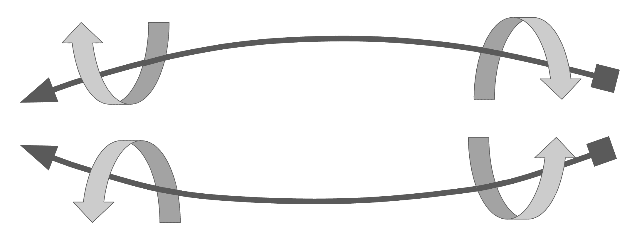
Torque-induced or gyroscopic precession is a fancy word used to describe any motion similar to that of a top i.e., any motion that rotates around a singular axis with an additional, external torque applied to it. In the case of an arrow, the shaft itself is the central axis, while the external torque is the circular lift. The resulting trajectory of an average arrow that experiences standard or general rotation in the diagram below.
After leaving your bow, an average arrow flies on a parabolic path and usually sticks the target at an acute angle. In the case of a gyroscopic procession, however, in an identical setup, the trajectory of flight is very different (below). Often, the slope of the latter end of the path is flatter, and the arrow itself “sticks” or ends up hitting your target head-on. This change, as aforementioned, is due that additional torque/force–circular lift–which feeds the rotational energy of the arrow. You can take advantage of this factor only through the use of Aerovane II and III due to its significantly high rotation rate.
Oscillation & Its Resulting Motion
Consider this—your arrow oscillates during flight. And during this oscillation process, a lot of energy is lost. This is because your shot arrow, as any object with energy, needs to reach an equilibrium.
The ideal arrow motion scenario (and unfortunately the one most believe to always be the case) is a linear flex through a center point where the first (red dot) and second dynamic bend (blue dot) are 180 degrees from one another. This would result in the expense of the minimum amount of elastic energy lost. Further, even if it was to flex in a parabolic motion [0, right] the true center of the shaft would always be maintained.
Unfortunately however, such a scenario is “ideal” and even a perfectly extruded aluminum arrow made with truly homogeneous material and a completely linear spine would not move in this fashion. To reach that “equilibrium,” an arrow, no matter how “perfect,” will sporadically flex and bend during flight. Exactly how sporadic that movement is during oscillation depends on how its three central resulting motions manifest and interact with one another. Note also that they all happen simultaneously.
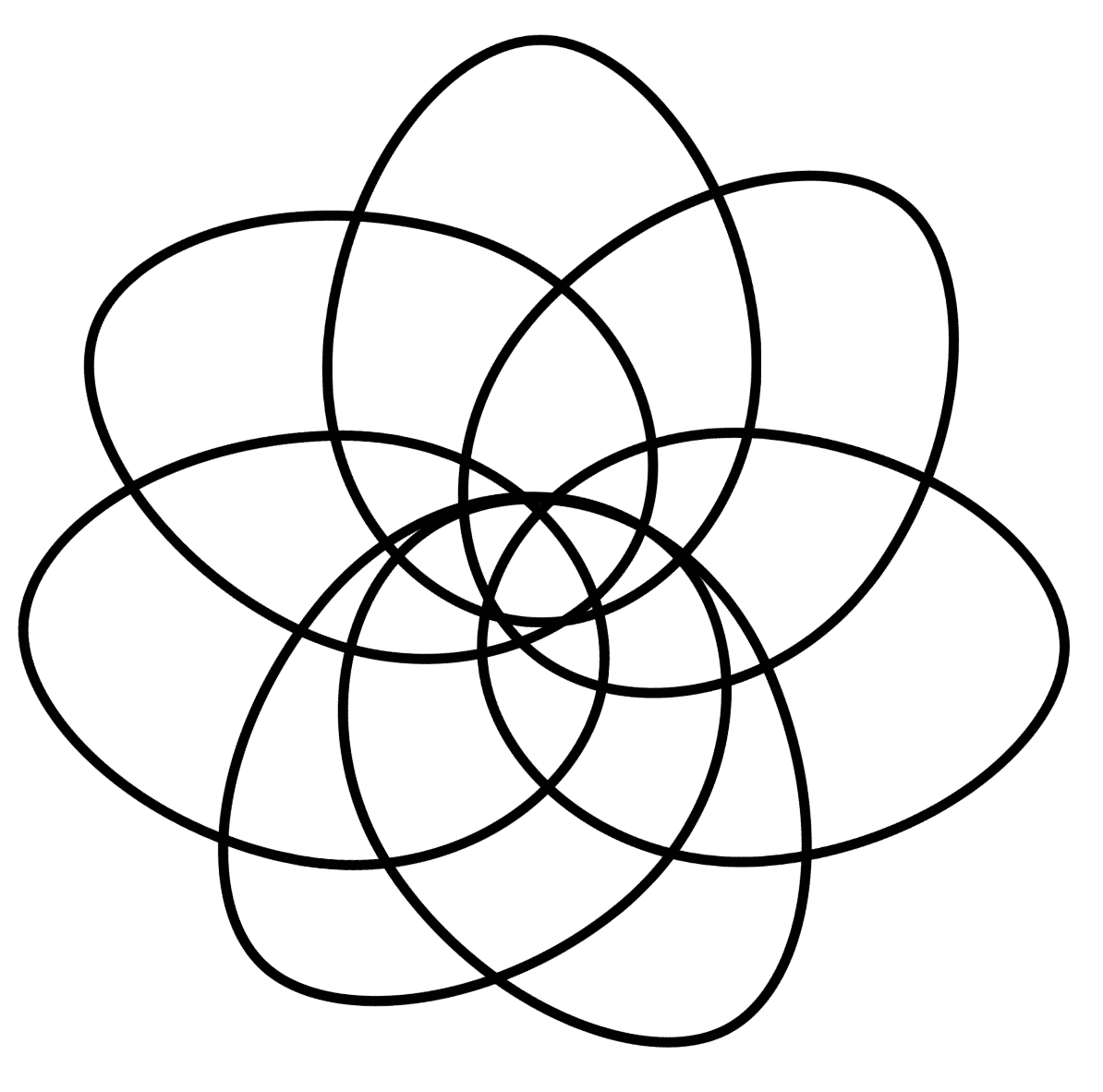
1. Actual linear flex occurs indeed through a first (red dot) and a second dynamic bend (blue dot), but not 180 degrees from one another. Instead, common pairings will be at something like twelve and four o’clock (120 degrees) or twelve and seven o’clock (-150 degrees). This motion results in the deformation of the center of the arrow from round to elliptical and many times, off-center elliptical.
2. Torsion, or opposite circular longitudinal flex occurs when an arrow is flexing linearly at both ends in two opposite directions. This motion is a byproduct of the previous motion, actual linear flex.
3. Finally, as another byproduct of actual linear flex, an off-center rotation occurs. This rotation is due specifically to the aforementioned deformation of the round shape of the shaft and follows a parabolic path.
All in all, by understanding the complex phenomenon that happens during arrow oscillation—by understanding the what and the why of each action—Firenock is able to develop and patent products like the AeroWeave.
Harmonic Dampening
The AeroConcept System (ACS) involves four elements, three of which are familiar to most—an arrow shaft, an insert, and a point (see diagram above). The last element of the ACS, unique to Firenock, is a “Carbon Inner Tube." This tube, as suggested, is made of carbon and is intended to sit within an arrow shaft. Specifically, its designed for installation with an AeroInsert-H to create one large insert unit. The question still remains however, why include this Carbon Inner Tube?
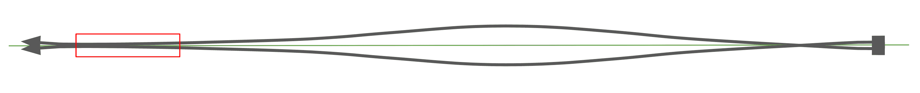
Well, the AeroConcept System, via this extra element, will not only strengthen your arrow’s front end, but also gives your arrow a variable spine (i.e. spine at the front and at the back are different). The first effect’s cause is obvious. By adding—i.e. gluing with the intention of melding—a new, smaller carbon tube into your shaft, the overall wall thickness increases at the front, stiffening and generally reinforcing it. The reason for the second effect, the variable spine, is a bit trickier. To explain, first recall the oscillation cycle (above but also added below for reference). Now, realize that due to the addition of the CTI, the spine is higher near the front than everywhere else. This distinction means that the radius of that oscillation is shortened significantly (below). And due to that shorter radius, the cycle of oscillation is dampened—in fact, harmonically dampened (US Patent: 9,395,166). Your arrow stops flexing significantly faster and thus begins flying flat faster. With your arrow equipped with the AeroConcept System and Aerovane II or III, it can even enter a gyro spin.
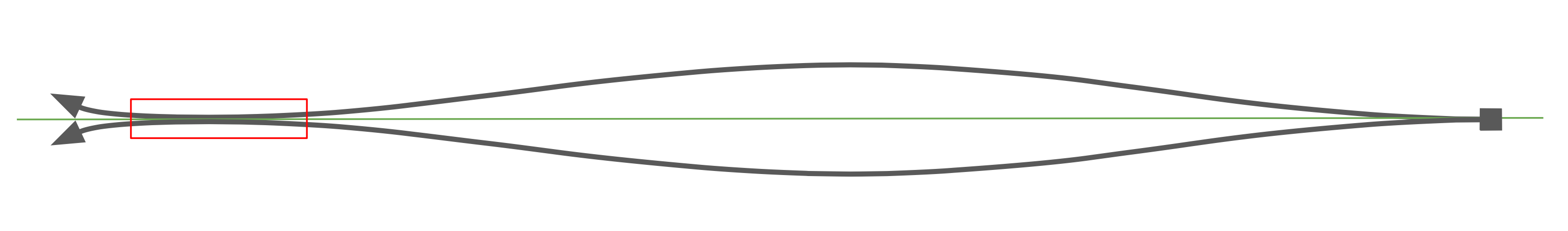
Additionally, an aftereffect of the AeroConcept System is how it extends a node into something we call a “null zone” (marked above in red). This shift allows for more arrow forgiveness since there’s an actual entire area to accurately position your arrow rest at pull back instead of a singular point. Learn more about why this matters from the AeroFlight 101 spread.
20210712 SH